 First released in 1990, the Master System II is a cost-reduced version of the original Master System, with some features removed to reach a lower price point.
Among the features removed, the selection of video outputs was heavily reduced so that only the RF modulator remained. Not only is this the lowest quality video output, you have to tune in the TV to get it working and it doesn't work at all with monitors and modern TVs.
The easiest solution to these problems is to modify the system for composite video/audio output. While composite isn't the highest quality video option available, it's better than RF and works on almost every TV made since the 80's (unless you have a "smart" TV with nothing but HDMI on the back, but such TVs often have disappointingly slow image latency anyway)
There are some SMS2 video mods already available, but as far as I'm aware, they all require some varying degree of bodge wires. In some cases, you have to drill holes into the case to make way for extra connectors. There's got to be a better way...
The good news is that the SMS1 and SMS2 both use the same type of IC for converting RGB into composite video and sending it to the RF modulator. (later SMS2s use an SMD equivalent that works exactly the same, as far as this mod is concerned)
On the SMS1, pin 20 (video out) and pin 9 (audio out) of this IC supply a signal to both the A/V connector and the RF modulator through two separate sets of voltage leveling circuitry.
Thanks to these fortunate circumstances, modifying the SMS2 for composite video is as simple as changing a few components to match the component path that supplies composite video to the SMS1's A/V connector
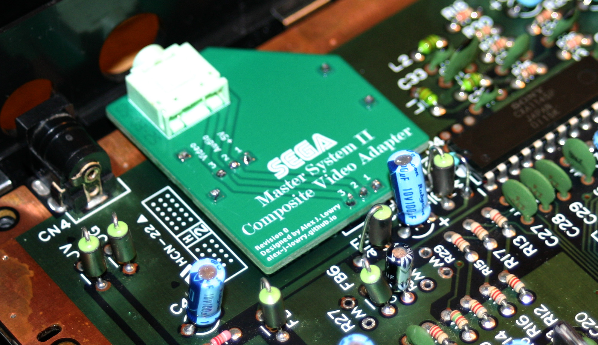
I have designed a PCB that fits in place of the RF modulator and provides audio and video out through a 3.5mm jack, accessible through the existing hole in the case intended for the modulator.. This can be connected to a display using a standard two-channel 3.5mm-to-RCA cable (usually sold for stereo audio applications).
The video output from this mod is free of any noise or "jailbars". To see screenshots of a modded system in action, see the link at the top of this page.
This modification is entirely reversible, if at some point you decide to return the system to its original configuration.
 The following instructions are currently applicable only to PAL Master System IIs manufactured in 1992 or earlier! (board revision IC BD M4Jr. PAL) If you have successfully installed this mod on an NTSC system or the later "IC BD M4Jr. PAL 2M" revision, I would appreciate if you could let me know your installation method via email, noting the polarity of the 10μF capacitor, so I can add it to this site - my address is on the homepage.
This mod is fairly easy to install, so long as you have decent desoldering skills and equipment. I recommend getting a Chinese T12 soldering station with temperature display (around $30 on eBay) and an Engineer SS-02 solder sucker (also around $30, but be aware there are a lot of clones on the market - however, they may work well enough for this purpose).
The SMS2's circuit board is decently good quality, but try not to be too heavy-handed while desoldering. You may find it easier to remove components if you carefully cut each component off of its leads before desoldering with wire cutters, so that each lead will fall out on its own.
Make sure all component leads are completely loose before trying to pull components out, especially the RF modulator; otherwise, you risk tearing solder pads off the board.
Before beginning, you'll need these components ready:
Now you can install the adapter PCB!
First, you'll need to solder pin headers to the adapter in all the holes that aren't used for the 3.5mm jack. The plastic parts should be underneath the PCB, since they raise the connector to the right height for the case hole.
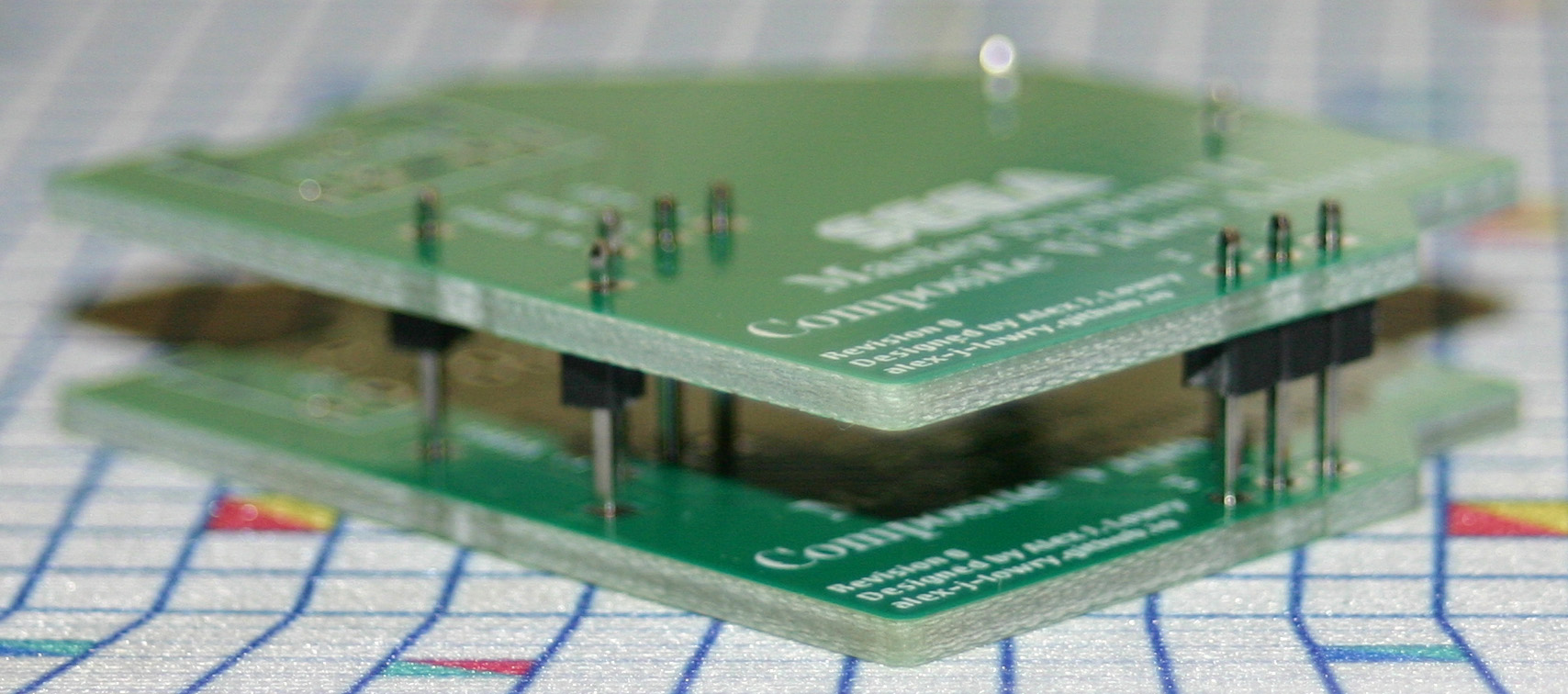 To keep the pins in place, you can use either one of the extra PCBs from the fabricator (if your fabricator required that you have more than one board manufactured) as seen in the photo on the right, or the former residence of the RF modulator on the Master System PCB.
Next, install the 3.5mm jack. Note that it helps to place the board on a piece of foam - such as the anti-static foam that ICs often come packaged in - to keep an even force on the connector as you solder it in.
Now that the adapter is ready, you can install it onto the Master System PCB. The foam trick also works well here, but note that there are no supports on the connector end of the adapter - therefore, the foam should be placed on the inward-facing end.
After soldering, cut off the excess length of the pin headers, especially if you installed the long side facing down as seen in the photo. Doing this ensures that the pins won't short out against the outer shielding.
Once the adapter is installed, your work is done! You can now reassemble the system, making sure to attach the heatsink back onto the 7805 regulator. Plug it in and give it a test - you should now have a working composite modded Master System II that looks no different on the outside than it did before!
![]() PCB Gerbers
PCB Gerbers
ZIP archive, 66.9 KB - This is the Revision 1 PCB. It's a slightly different shape than the Rev. 0 prototype seen in the photos to give it some extra rigidity, has a ground plane on both sides of the PCB for extra noise reduction and has a more accurate silkscreen (the "Video" and "Audio" labels were accidentally swapped on the prototype).
![]() KiCad Files
KiCad Files
ZIP archive, 2.21 MB - Useful if you want to make modifications to the PCB. Made with KiCad 9.
![]() Custom Fonts
Custom Fonts
ZIP archive, 47.9 KB - Custom fonts used for the KiCad files. Only needed if you want to modify them.
![]() Other Schematics
Other Schematics
ZIP archive, 3.36 MB - The schematics for both variants of the Master System, courtesy of SMS Power.
Last updated on Mar 23, 2025.
This page was first uploaded on Mar 23, 2025.
visitors since Dec 26, 2025.