
 A composite color video signal is difficult to produce without specialized components made specifically for the purpose. The color information has to be embedded into the luminance signal in a way that doesn't interfere with black-and-white display compatibility. It's remarkable that this problem was solved as early as the 1950's!
For this reason, some computers in the 1980's (mainly those from the USSR) would only output color video through RGB with a separate sync signal at 5 volts peak-to-peak to reduce the amount of components required.
In the 1990's, a company in Moscow released the NIMF-4, a device that could convert such a signal into composite video with PAL color encoding. This implementation was based entirely on common off-the-shelf components, and every component (excluding the 8.87 MHz crystal oscillator) is still manufactured today.
As was common at the time in Russia, the company that manufactured this encoder removed the markings from ICs to prevent cloning. In 2023, the NIMF-4 was reverse-engineered by Alexey Zhabin, who published a schematic and PCB for an upgraded version with S-Video.
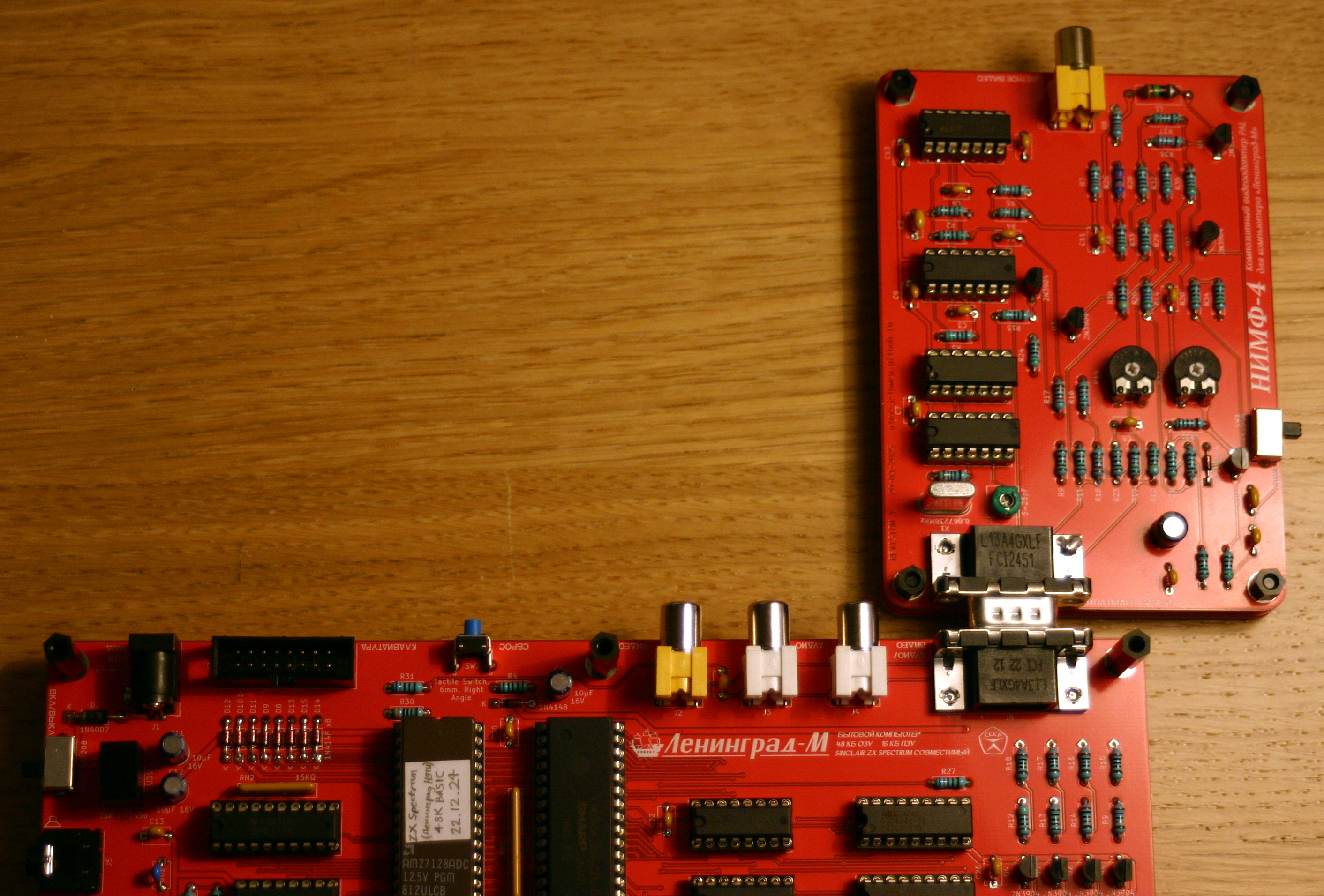
I've designed a PCB based on this schematic with a DE-9 input connector that can be connected directly to my Leningrad-M computer without cables. To reduce the component count and PCB size, I've designed it without the S-Video connector, though I may add one to a future revision if there's interest.
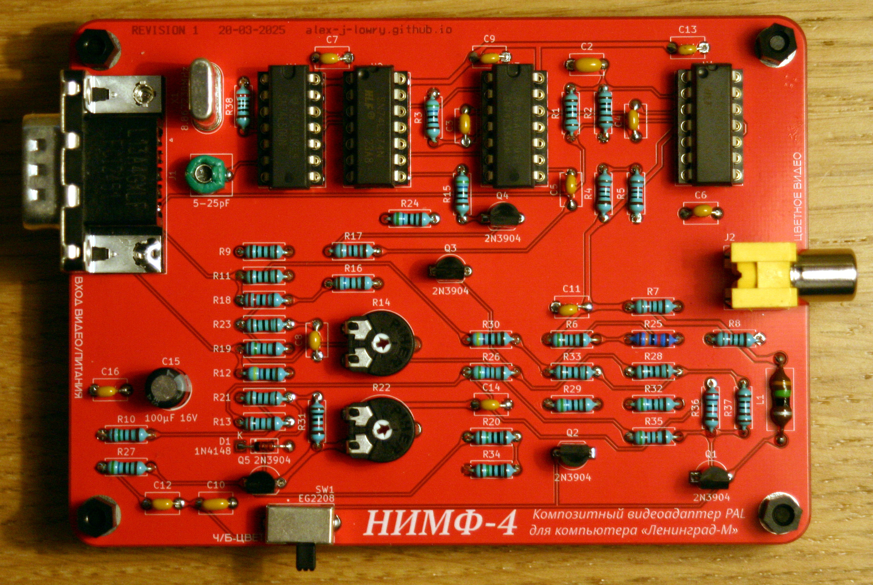 The encoder has 3 adjustable components. R14 and R22 adjust the color balance, while C1 adjusts the color burst frequency. You won't get a stable color signal until all 3 of these are tuned in, but you don't need any special measurement equipment for tuning.
The switch can be used to disable color generation so that only a monochrome signal will be generated, which I've found to be useful for troubleshooting. If you want to save having to buy the switch, you can connect the solder pads for the switch with a jumper wire.
The original schematic calls for 1.5K potentiometers for R14 and R22, and a 5-25 pF variable capacitor for C1. Due to the scarcity of parts with these specific values, I opted to use 1K potentiometers and a 6.5-30 pF capacitor, which seem to work just as well.
It should be possible to connect it to other computers, but you'll need to make a custom cable to do so.
For a computer to be compatible, it should have separate red, green, blue and sync signals, all at approximately 5 volts peak-to-peak (5V high, 0V low). The sync signal should be active low.
Here's the pinout of the input connector.
DE-9 Pin Number |
|
1 |
|
2 |
|
3 |
|
4 |
|
5 |
|
6 |
|
7 |
|
8 |
|
9 |
|
Shield |
Keep in mind that pin numbering on male and female D-Sub connectors is mirrored. Pin 1 will always connect to Pin 1 on the opposite connector, Pin 2 to Pin 2, etc.
![]() My Schematic
My Schematic
PDF document, 656 KB
![]() My PCB Gerbers
My PCB Gerbers
ZIP archive, 324 KB
![]() KiCad Files
KiCad Files
ZIP archive, 865 KB - Useful if you want to make modifications to the PCB. Made with KiCad 9.
![]() Custom Fonts
Custom Fonts
ZIP archive, 1.36 MB - Custom fonts used for the KiCad files. Only needed if you want to modify these files.
![]() Source Schematic
Source Schematic
PDF document, 343 KB - Alexey Zhabin's reverse-engineered schematic, with S-Video circuit.
![]() Source PCB Gerbers
Source PCB Gerbers
RAR archive, 34.1 KB - Alexey Zhabin's PCB layout, with S-Video output. Uses a DIN-8 connector for video and power input.
Last updated on May 13, 2025.
This page was first uploaded on May 13, 2025.
visitors since Dec 26, 2025.